Navigation

    LILYGO

    • Register
    • Login
    • Categories
    • Recent
    • Tags
    • Popular
    • Users
    • Groups

    How to flash T-01C3

    Product information
    2
    16
    1290
    Loading More Posts
    • Oldest to Newest
    • Newest to Oldest
    • Most Votes
    Reply
    • Reply as topic
    Log in to reply
    This topic has been deleted. Only users with topic management privileges can see it.
    • M
      m4biz last edited by m4biz

      Hi.
      I've just purchased an T-01C3 board.
      I don't know how to flash it.
      May you help me?
      T-01.png

      teastain2 1 Reply Last reply Reply Quote 0
      • teastain2
        teastain2 @m4biz last edited by

        @m4biz You need a USB to ttl converter called an ISP and it connects to the port on the end opposite the antenna.
        Sometimes erroneously called a FTDI.
        I have several, but this is my new baby!:
        https://docs.m5stack.com/en/module/StampISP

        M 1 Reply Last reply Reply Quote 0
        • M
          m4biz @teastain2 last edited by

          @teastain2
          Hi.
          Thanks for your reply.
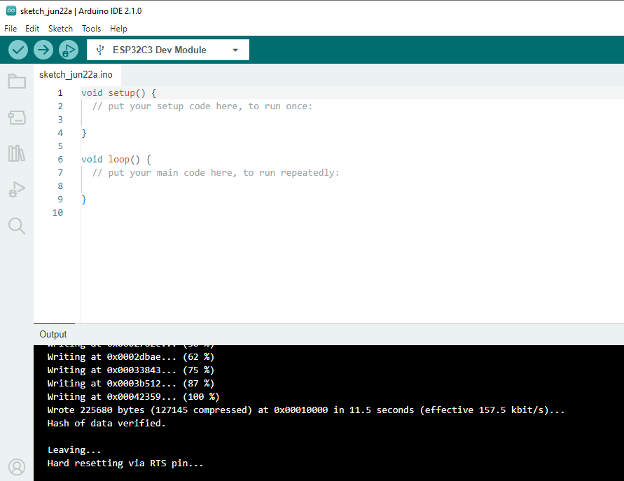
          I've USB to TTL converter but when I try to upload an arduino's sketch I receive this error:
          56ee4dde-cdd7-41c3-a23e-6e9a099ce6a4-image.png
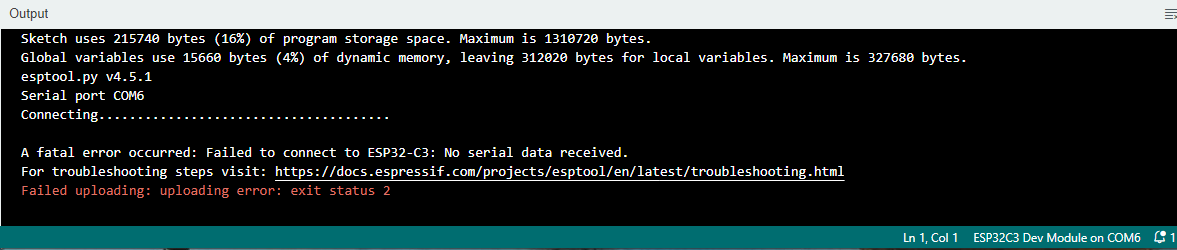
          I think it depend on the card must be in boot mode (like pushing a button on other kind of ESP32 cards) but here there are no buttons,...
          How do you put the card in boot mode so that may you flash it?

          teastain2 1 Reply Last reply Reply Quote 0
          • teastain2
            teastain2 @m4biz last edited by teastain2

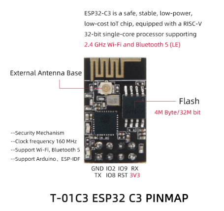
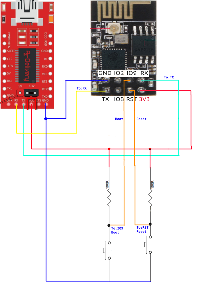
            @m4biz GPIO9 is boot and rst is Reset.
            You have to break these out to a breadboard and strap GPIO9 with a 10K to 100kohm pull up resistor and the same with reset. Shorting the Boot (9) to ground and then short reset to ground momentarily and then release Boot should put you into boot mode.
            At the risk of hindsight I ALWAYS buy a board with USB !!!
            This is my M5Stamp C3:
            https://shop.m5stack.com/collections/m5-controllers/products/m5stamp-c3-mate-with-pin-headers
            USD$ 6.00 (!)

            Here is the LilyGO T-Display S3 arrangement where Boot is GPIO 0:
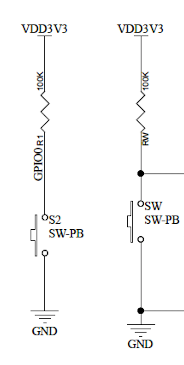
            Screenshot 2023-06-18 at 5.00.51 PM.png image url)

            M 1 Reply Last reply Reply Quote 0
            • M
              m4biz @teastain2 last edited by

              @teastain2
              Hi. Thanks for you reply again.
              This my configuration:
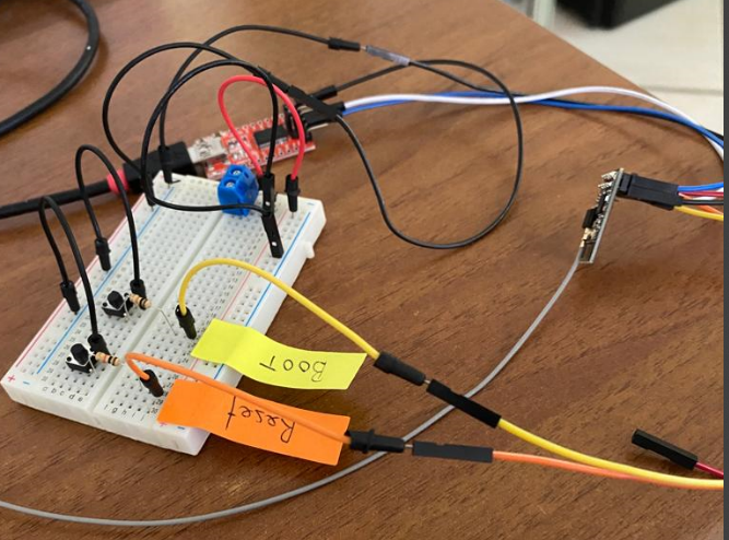
              e2d198ef-6b31-4331-8b6d-ea8182b2a228-image.png
              Anyway.
              I've tried to press :

              1. Boot
              2. Reset (while boot is pressed)
              3. release Reset (while boot is pressed)
              4. release Boot
                But nothing change.
                I receive the same error.
                Where am I wrong ?
              teastain2 1 Reply Last reply Reply Quote 0
              • teastain2
                teastain2 @m4biz last edited by

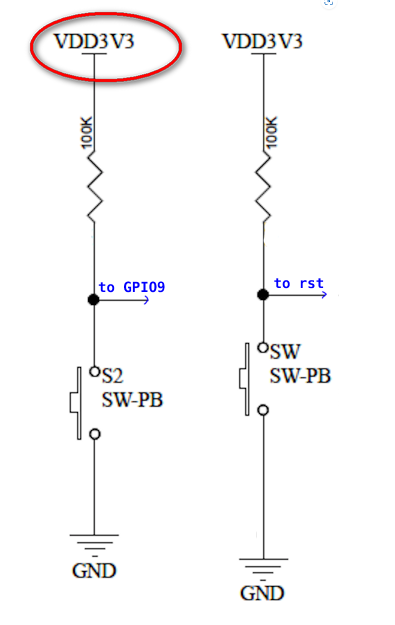
                @m4biz The circuit that I sent you was not drawn very clearly by LilyGO, So I edited it:Strapping.png
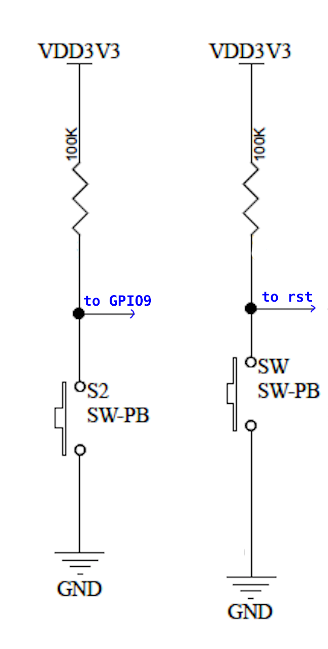
                Your image shows the Boot and Reset in series with the resistor.
                The top of the resistor should be on v3.3 and the lead should be on the switch side of the resistor.
                -Terry

                M 2 Replies Last reply Reply Quote 0
                • M
                  m4biz @teastain2 last edited by

                  @teastain2
                  Ok.
                  I'll try.
                  Thanks for now.

                  1 Reply Last reply Reply Quote 1
                  • M
                    m4biz @teastain2 last edited by

                    @teastain2
                    Hi.
                    When you say VDD3V3, you mean:
                    a) that on the FT232-AZ USB auf TTL adapter:
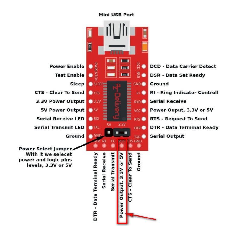
                    47cc5bf3-c6fd-462b-bac5-81f3a8c11168-image.png

                    or
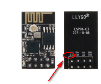
                    b) that on the LilyGO ESP32 module:
                    688c610d-e08c-4c8e-bc8d-5b69fb696098-image.png

                    teastain2 1 Reply Last reply Reply Quote 0
                    • teastain2
                      teastain2 @m4biz last edited by

                      @m4biz The USB adapter is powered by 5v, obviously, and the ESP32 needs 3.3v.
                      Arduinos such as Arduino Uno and other Atmel chipped boards use 5v, so this option needs to be set to 3.3v for ESP32!
                      I did not know your TTL had this option, so set it to output 3.3v.

                      M 1 Reply Last reply Reply Quote 0
                      • M
                        m4biz @teastain2 last edited by m4biz

                        @teastain2
                        Shure, the adapter is set on 3.3 V.
                        Anyway, in the circuit you have uploaded I see VDD3V3
                        c50dff8c-931e-44d8-8bb4-fa30ce5fbec9-image.png
                        I don't know where must I take this voltage from the ESP32 module or from the FT232 adapter ?

                        teastain2 1 Reply Last reply Reply Quote 0
                        • teastain2
                          teastain2 @m4biz last edited by teastain2

                          @m4biz VDD and VCC are typical power supply markings in electronics.
                          The number VDD3V3 means 3.3v, which is a standard for all ESP32s and almost all new sensors.
                          Your board needs to be powered somehow, so set the TTL to 3.3v. The TTL will power the board.
                          After uploading your sketch you will need the TTL connected to power it, or you will have to get a standalone 3.3v power supply.

                          M 1 Reply Last reply Reply Quote 0
                          • M
                            m4biz @teastain2 last edited by

                            @teastain2
                            Nothing to do.
                            I've tried all but don't works.

                            teastain2 1 Reply Last reply Reply Quote 0
                            • teastain2
                              teastain2 @m4biz last edited by

                              @m4biz
                              Thank you for responding, I'm still willing to help.
                              It is ironic that these cheap "AliExpress" boards, like LilyGO and Lolin save you 3$ by not getting the USB model but require much more advanced experience to handle. I see this ALL THE TIME.
                              Even new guys with a ESP32 S3 latest board WITH USB will still be difficult to get a sketch downloaded and run.
                              I have been with Arduino for 10 years and these new boards are very difficult, not Plug'n'Play!
                              I could draw out a complete circuit for you, I f you like.
                              Also...does the Arduino IDE even recognize the port?

                              teastain2 1 Reply Last reply Reply Quote 0
                              • teastain2
                                teastain2 @teastain2 last edited by teastain2

                                @teastain2
                                LilGO-TTL1024.png
                                (you need to cross over TX to RX so that the TTl TX is the LilyGO RX !)

                                M 1 Reply Last reply Reply Quote 1
                                • M
                                  m4biz @teastain2 last edited by

                                  @teastain2
                                  Wonderful!!!
                                  Works.
                                  Thanks for you time.
                                  e826e24d-f8d0-47ad-95e5-1f0dbc578578-image.png

                                  teastain2 1 Reply Last reply Reply Quote 1
                                  • teastain2
                                    teastain2 @m4biz last edited by

                                    @m4biz Fantastic news!

                                    You can also put a small
                                    delay(500);
                                    In the loop to keep it from locking up and becoming very hard to upload another sketch!

                                    But: GREAT JOB !

                                    1 Reply Last reply Reply Quote 0
                                    • First post
                                      Last post
                                    Powered by NodeBB | Contributors