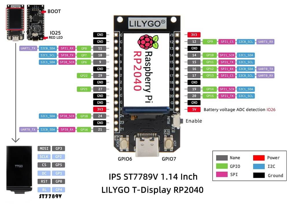
Friends, I'm programming a LilyGo with an RP2040 processor and a 1.4 inch display for the first time, but I can't program the display!

I tested various codes and libraries such as TFT_eSPI, Adafruit GFX and Adafruit_ST7789, taking care to correctly configure the pins, and the result is always the same:
The code loads, the port 25 led blinks normally, and the serial output of the Arduino IDE prints "On" and "Off", but the display gives no sign of life.
The board is brand new and works perfectly with factory settings, but I can't get the display to work with my codes, and neither can the sample codes from any of these libraries.
Does anyone have an idea what could be wrong?
/*
| Pins |
RP2040 |
| TFT Driver |
ST7789(240*135) |
| TFT_MISO |
N/A |
| TFT_MOSI |
3 |
| TFT_SCLK |
2 |
| TFT_CS |
5 |
| TFT_DC |
1 |
| TFT_RST |
0 |
| TFT_BL |
4 |
| PWR_ON |
22 |
| BOTTON1 |
6 |
| BOTTON2 |
7 |
| RedLED |
25 |
1 - GP0 - I/UART0_RX - I2C0_SDA - PWM
2 - GP1 - UART0_TX - I2C0_SCL - PWM
3 - GP2 - UART1_TX - SPI1_SCK - PWM
4 - GP3 - UART1_RX - SPI1_MOSI - PWM
5 - GP4 - SPI1_MISO - PWM
6 - GP5 - SPI1_CS - I2C0_SDA - PWM
7 - GP6 - IO - PWM
8 - GP7 - IO - PWM
9 - GP8 - IO - PWM
10 - GP9 - IO - PWM
11 - GP10 - IO - PWM
12 - GP11 - IO - PWM
13 - GP12 - IO - PWM
14 - GP13 - IO - PWM
15 - GP14 - UART1_RX - SPI1_MISO - PWM
16 - GP15 - UART1_TX - SPI1_CS - PWM
17 - GP16 - IO - PWM
18 - GP17 - IO - PWM
19 - GP18 - IO - PWM
20 - GP19 - IO - PWM
21 - GP20 - IO - PWM
22 - GP21 - IO - PWM
23 - GP22 - IO - PWM
24 - GP26 - IO
25 - GP27 - IO
26 - GP28 - IO
27 - GP29 - IO
28 - GP30 - IO
29 - GP31 - IO
*/
#include <Adafruit_GFX.h> // Include the Adafruit GFX library
#include <Adafruit_ST7789.h> // Include the Adafruit ST7789 library
#define TFT_MOSI 3
#define TFT_MISO 14
#define TFT_SCLK 2
#define TFT_BL 4 // LED backlight
#define TFT_CS 5 // Chip select control pin D8
#define TFT_DC 1 // Data Command control pin
#define TFT_RST 0 // Reset pin (could connect to NodeMCU RST, see next line)
#define LAMP_X 80 // Define the X coordinate of the lamp
#define LAMP_Y 80 // Define the Y coordinate of the lamp
#define LAMP_WIDTH 50 // Define the width of the lamp
#define LAMP_HEIGHT 80 // Define the height of the lamp
const int LED_PIN = 25;
const int t=1000;
Adafruit_ST7789 tft = Adafruit_ST7789(TFT_CS, TFT_DC, TFT_RST); // Initialize the TFT display
void setup() {
Serial.begin(115200);
pinMode(TFT_BL, OUTPUT); // Set the TFT backlight pin as an output
digitalWrite(TFT_BL, HIGH); // Turn on the backlight
pinMode(LED_PIN, OUTPUT);
tft.init(135, 240); // Initialize the TFT display with 240x240 resolution
tft.fillScreen(ST77XX_BLUE); // Fill the screen with blue color
}
void loop() {
digitalWrite(TFT_BL, HIGH); // Turn on the backlight
digitalWrite(LED_PIN, HIGH);
tft.fillRect(LAMP_X, LAMP_Y, LAMP_WIDTH, LAMP_HEIGHT, ST77XX_BLUE); // Fill the lamp area with blue color
Serial.println("On");
delay(t); // Wait for 1 second
tft.fillRect(LAMP_X, LAMP_Y, LAMP_WIDTH, LAMP_HEIGHT, ST77XX_YELLOW); // Fill the lamp area with yellow color
digitalWrite(LED_PIN, LOW);
Serial.println("Deleted");
delay(t); // Wait for 1 second
}
Thanks for the help!
