No GPS data received: check wiring
-
If I try any of the GPS examples code, on a T-Beam Supreme S3 L76K GPS version, I get
No GPS data received: check wiringin the serial monitor window.
I thought any of the examples would work out the box, but clearly not.
I'm using IDE 2.3.2 on macOS
Can anyone point be in the right direction?
-
@wellco Hi, I am just a community contributor, but I am usually all there is and I don't have one of your boards to test!
What exact GPS sketch are you using? 'TinyGPS' gives that error because the char received timeout is 5 seconds.
This could be if your unit is indoors.
If you are outdoors, try doubling the timeout.
-Terry -
@teastain2 Thanks for contribution.
I think the example I was using was not a good example. At least that's how it seems. Since my post last I have seen that there are two lots of examples folders:
../LilyGo-LoRa-Series-master/lib/TinyGPSPlus,
and
../LilyGo-LoRa-Series-master/examples/GPS/
Which is a bit confusing.
Anyway the folder ../examples/GPS/ has two lots of examples, one for the L76K and one for the Ublox.
So I am using
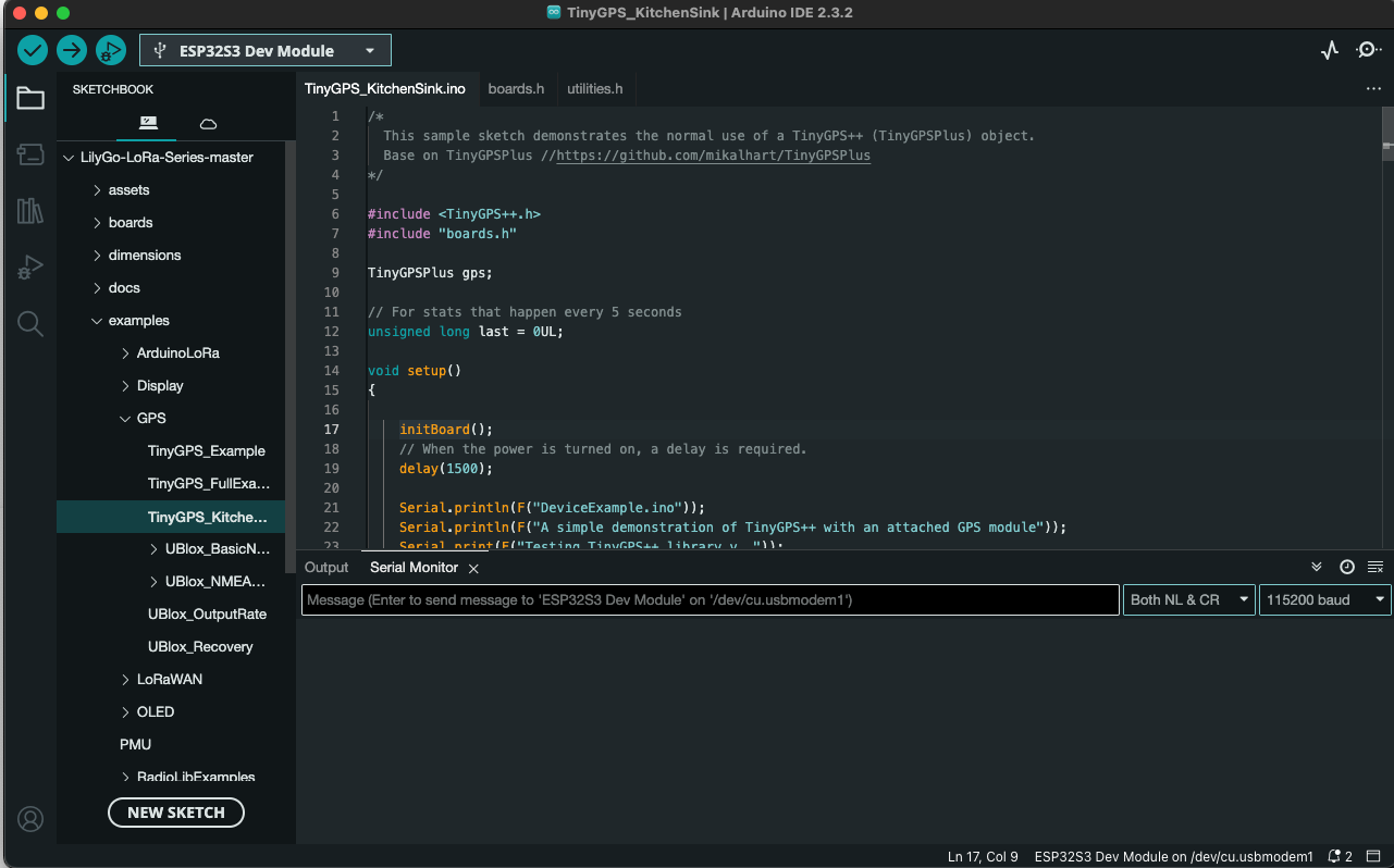
../LilyGo-LoRa-Series-master/examples/GPS/TinyGPS_KitchenSink ( I think this is correct for my board with the L76K GPS module)
This example gives me a different problem though. It runs the initBoard function but never returns to void setup() where it should print out some simple header info. Well nothing appears in the serial monitor window.
So while I haven't resolved my original issue I think I should probably go with the example that's specific to my GPS module (L76K).
This is the first time I have ever tried to program an Arduino/ESP32 so sorry if I am asking making a schoolboy mistake..
Many thanks, Wellco
-
@wellco ..answering myself here, it may help others.
I now have the right output in the serial window. Many frustrating hours were spent trying to make it work. Somehow Tools\USB CDC On Boot: Enable, had reset to disabled. It took me a while to realise this.
Then (this is the vague bit) sometimes I need to click the RST, Boot and Power buttons in various sequences. This is what usually works if the serial monitor window is blank.
- Press the RST button momentarily and wait for 20 seconds. If window is still blank ..
- Press the power button and hold for 6 secs. Release and press momentarily, wait for 20 seconds. If window is still blank ..
- Unplug the USB hold down the Boot down and plug the USB cable back in. Upload you sketch again.
- Hurl device against a solid wall with as much force as you can muster

Joking apart; there is also another button sequence that might help and that's the documented one. Hold RST down, press and hold the Boot button. Release the RST button, and finally release the Boot button.
Hope this helps somebody..
Cheers Wellco