T-ZigBee ESP32/tlsr8258 serial comms via DIP switches?
-
@teastain2 "this repository" being which one?
I do have one suspicion that occurred to me this morning. I wonder if this is a speed/electronics issue. I have been trying to use 1000000 baud and it seems that plugging in the T-U2T seems to help which makes me wonder if a slow baud rate would work and the "interesting" circuitry around the DIP switches has some floating lines or interesting electrical reflection at high speeds. I'm going to try slower baud rates this evening and see if that helps.
FYI the reason for using the 1000000 baud rate is that it is 8 times faster than 112500 and that means OTA/serial updates to the tlsr825 are 8 times faster. Long term my project will be downloading firmware to the ESP32c3 and then using the OTA/serial update process to update the tlsr8258. -
@papadeltasierra Sorry, forgot to paste the link!
https://github.com/Xinyuan-LilyGO/T-ZigBee
Yeah, maybe slow it down for testing!
cheers
-Terry -
@teastain2 I'd seen that repo before and the ESP32c3 code is identical, at least for the UART sections, in my code. I've programmed ESP32s before so I'm pretty certain the code is correct, especially since this all works fine providing I don't try and use the connection via the DIP switches.
I did try 115200 baud this evening and that doesn't work either... unless I plug in the T-U2T and plug that through to my PC. Looking at the schematics for the T-ZigBee board, I'm really struggling to understand what plugging in the T-U2T does but I keep coming back to the idea that the circuitry is a "Y" between the tlsr8258, the ESP32c3 and "something else", and the "something else" is floating/reflecting signals/doing something else bad and that plugging in the T-U2T somehow quenches it.
I have also tried both plugging in a USB-C power supply (still doesn't work) and the T-U2T with the power supply then plugged into the T-U2T and neither of these work. I have to have the T-U2T plugged in the the T-U2T plugged into the PC.
This is very disappointing because I am trying to create a small product that requires set-up and it appears I will have to wire from alternate tlsr8258 to ESP32 pins to get the serial connection to work.
If you have any suggestions as to what else to try, I'm all ears! -
@papadeltasierra Hmmm...Even though the board comes with a type-C socket, it does not have a USB chip on board. The type-C socket is for power and...the T-U2T is the USB chip. So, they expect you to un-plug your USB cable and insert the T-U2T in-between.
That may be why you cannot upload your program without the T-U2T!? -
@teastain2 Upload, absolutely agree. I did have a very "left field" thought this morning. I wonder if the tlsr8258 boots up in "USB mode" and plugging in the T-U2T makes it negotiate to Serial mode which then makes things work.
In the repo that you referenced, the tlsr8258 firmware is just "a binary blob" so I cannot see what it does but I will take a long look at my tlsr8258 code this evening. I know there are options to enable to tlsr8258 library's ZBHCI interface (the way you control the ZigBee operations of the board) so maybe I've set one of those wrongly. -
@papadeltasierra So I looked at the tlsr8258 code and I cannot see anything wrong with it (yet?). It is requesting UART mode, using the correct pins etc.
I do have two additional bit of information though. Firstly I have discovered that I do not require the T-U2T to be plugged in; just connecting a USB cable directly from the T-ZigBee to my PC is enough to make things work. I'm really struggling to understand why though!
Secondly, with the USB cable plugged in, it appears that the serial data is somehow relayed EVEN if the DIP switches are all set to "off". This makes absolutely no sense since the schematics imply that there is no connection between PB1/7 and GPIO18/19 unless the DIP switches 2-5 are "On".
I am sure that the "reflection" that seems to happen without the USB cable (everything the ESP32c3 sends towards the tlsr8258 is returned back) is trying to tell me something but I am darned if I can see what! This "reflection" seems to happen EVEN IF the DIP switches are "Off" which again makes no sense at all.
I'm at a total loss as to what is going on here. I rather hope some LilyGo tech. might see this post and suggest something!
-
@papadeltasierra Sigh. Just realised that the T-ZigBee schematic I have must be wrong. It shows no connection from the USB socket to the tlsr8258, which has to be wrong. Do you believe there is one and if so, how?
-
@papadeltasierra Ok, consider this:
UTX is dip selectable, as you know.
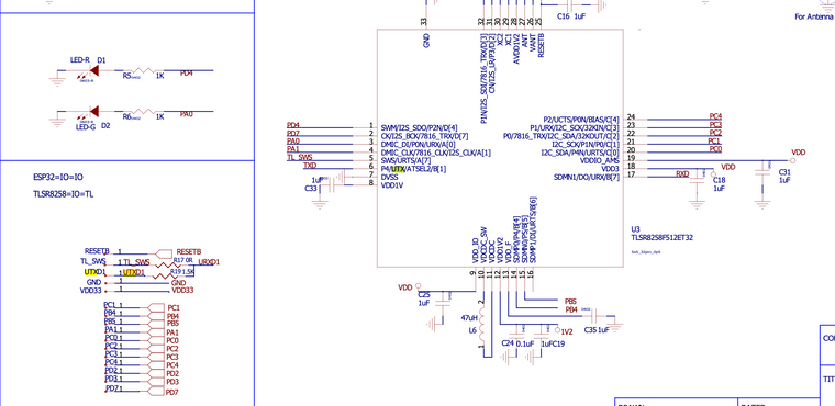
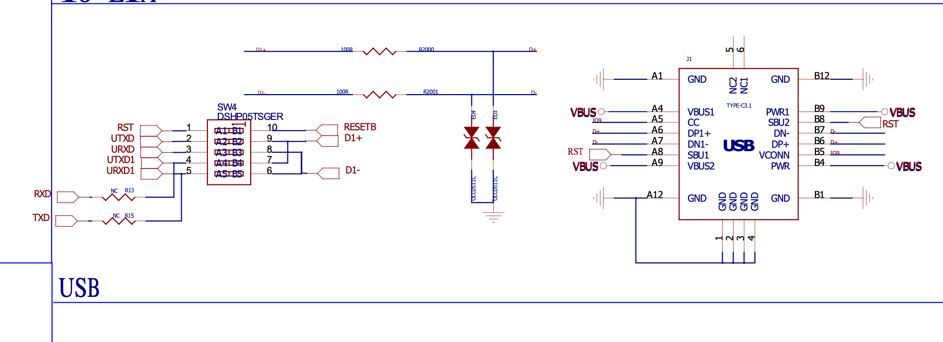
It must direct the U-T2T flow to the tlsr8258.here are some snips fro the schema:


-
@teastain2 Thanks - this matches the schematic diagram that I have been looking at. I read the diagram as follows - am I wrong?
- The DIP switch has the USB-C connector to the right side and the boards to left
- I have no idea at all what the USB chip is doing there and I can't see where it is on the physical board either - is this actually some part of the T-U2T?
- The connections left of the DIP for RXD/TXD show R13/15 as "nc" which normally means "not connected" but RXD/TXD are PB1/7 so how might anything reach them?
- If the DIP switches are "off" (I assume meaning no connection through) then there should be no connection to the USB-C so plugging in the USB-C should have no affect, but it does!
I am wondering whether the "reflection" I see is actually via the IRDX1/UTXD1 and the resistors R17/19 on the JTAG layout. Perhaps this implies that maybe plugging the USB-C in perhaps pulls down TL_SWS (though I have no idea how!), meaning that the bleed through is quenched and the RX/TX (no idea which actual pins!) of the tlsr8258 can then function as expected, free of the bleed-through.
I've raised an issue on the repo that the schematic comes from, questioning whether the schematic is correct - perhaps I will get an answer there.
-
@papadeltasierra Aha, just spotted that the schematics appear to match the published pictures of a T-ZigBee, in which the board is marked V1.0. However my board is clearly different and is marked V1.2. There is no "USB" chip for example so I am wondering what other changes have been made to the board.
-
@papadeltasierra Umm, might be that I have confused the T-ZigBee and T-ZigBee PA boards, although I still don't see where the "USB" chip is!
-
@teastain2 Ok, so I got out my webcam, digital camera and lights and traced the traced the tracks on the T-ZigBee. It is impossible to 100% accurately follow the USB connections as they are hidden under the LIPO connector but I can see that PB1/7 and GPIO18/19 have direct connections and then also spurs off to the NC resistors (there are empty spaces for them) mentioned in the schematic. Of course this is even more confusing because it means that plugging in the USB connector cannot be affecting this pathway which implies it much be somehow changing the behaviour of either the ESP32c3 or tlsr8258's pins!
This does explain why the DIP switches have no effect though, because this direct connection does not go via them. So I would expect the serial connections to work if the DIP switches were "all off". -
@papadeltasierra Latest bit info - "USB" on the schematics is the USB-C connector, which explains why the left and right sides are identical - whichever way you insert the connector, it connects the same way around.
I also suspect that the reflection I see is GPIO20/21 being joined via the TLS_SW and resistors shown on the schematic. I suspect that none of the comms is actually via the ESP32/tlsr8258, rather these resistors might be wiring the FDTI back onto itself. I am going to try using different GPIOs instead of GPIO20/21 and test for two things:- Does "through the ESP32/tlsr8258" comms then run even without a USB-C plugged in
- Does GPIO21/20 reflection happen even if there is no ESP32 code involved, which would prove it is a physical connection rather than software.
Still struggling to see how plugging in a USB-C would change the electrical characteristics of the GPIO20/21 connection though, if that is indeed the issue.
-
@papadeltasierra Well, Papa, I think the ESP32-C3 has a 'FTDI' style USB converter chip built in to the silicon, and the tlsr8258 certainly does not and therefore you require the T-U2T gizmo to convert USB info into the tlsr8258.
To do this you have to set switches to control the flow of program AWAY from the ESP32-C3, towards the tlsr8258.
-Terry -
@teastain2 The issue is apparently somehow to do with GPIO20/GPIO21. I changes the ESP32c3 software to relay between GPIO7/8 and GPIO18/19 and the relay works fine, even without the USB cable plugged in. According to the schematics, GPIO20/21 are just connected to the pin bank and the DIP switches but with the DIP switches "off" there should be no connection through to the USB. So I have a solution but I am totally lost as to why :-(.
-
@papadeltasierra BTW the ESP32c3's USB mode is disabled; unless you enable it, it should run as a standard serial port (which is what I am now seeing).
-
This post is deleted!